
- #NUCLEO F401RE USB DEVICE HOW TO#
- #NUCLEO F401RE USB DEVICE INSTALL#
- #NUCLEO F401RE USB DEVICE SERIAL#
- #NUCLEO F401RE USB DEVICE MAC#
- #NUCLEO F401RE USB DEVICE WINDOWS#
To find out your numbers first plug your USB device and then type lsusbīus 002 Device 007: ID 041e:323d Creative Technology, Ltdīus 002 Device 005: ID 04d9:1702 Holtek Semiconductor, Inc. If you have different programmer you should change idProduct and idVendor. Next thing is to add proper permission to new devices.Īfter opening les (you can chose number to be anything integer under 99) file in nano, paste following rules for different ST-Link devices.ĪTTRS="0483", MODE="666", GROUP="plugdev" After installation run Eclipse and install plugin for STM32 procesors development. Follow this instruction .
#NUCLEO F401RE USB DEVICE INSTALL#
Sudo add-apt-repository ppa:team-gcc-arm-embedded/ppaįirst install Eclipse IDE ( ). Now we need compiler, linker and assembler (toolchain) for ARM Cortex architecture ( ). If you using Ubuntu or any Debian like OS, OpenOCD could be installed by running following command: Terminal sample application output (Mac/Linux), e.g.The Open On-Chip Debugger (OpenOCD ) aims to provide debugging, in-system programming and boundary-scan testing for embedded target devices. The correct USB device name can be determined by entering the command ls /dev/tty.usbmodem* in a shell.
#NUCLEO F401RE USB DEVICE MAC#
“Tera Term” sample application output (Windows): Mac
#NUCLEO F401RE USB DEVICE SERIAL#
Once you have found out the serial port number, open “Tera Term” and specifiy the port number and Baud rate via “Setup” > “Serial port…”:
#NUCLEO F401RE USB DEVICE WINDOWS#
The correct USB modem COM port can be determined in the Windows “Control Panel” > “Device Manager” from the “Ports (COM & LPT)” entry: Two parameters are required to use the Virtual COM connection on the host: This serial communication is forwarded to the host by the ST-Link debugger via a USB Virtual COM connection and can be used with a terminal program. To allow serial print debugging, the target serial wires ( CN3, PA2+PA15) are connected to the ST-Link debugger. Connect target serial UART to host terminal If LD1 is lit red, no target connection could be established. LD1 quickly flashes for a few seconds and switches to green (connected). Completed setupĪfter all modifications have been done to the Nucleo board, according to the instructions above, the target board can be connected via the 8-pin adapter cable: Load firmware to targetĭrag and drop the “.bin” file containing the firmware to the Nucleo USB drive (“NODE_L476RG”): The ST-Link LD1 should light up, and the USB drive “NODE_L476RG” is mounted on the desktop.

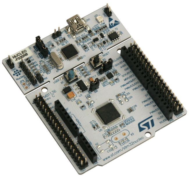
Another option is to break off the ST-Link part (see white dotted line in the Nucleo board figure above). Using the RX/TX/RST/SWO lines between a remote target and the Nucleo board ST-Link interface requires desoldering the 0 Ω bridges on the underside of the Nucleo board (see figure below). Preparation and connection of the adapter cableĪn 8-pin adapter cable acts as an ST-Link cable and is required to connect the Nucleo board to the target: Signalĭebug connector, VDD is not needed and may result in reverse current, therefore leave it open
#NUCLEO F401RE USB DEVICE HOW TO#
This document describes how to use a Nucleo STM32L476RG board to connect to a target STM MCU for firmware downloading, debugging and serial terminal connection.


 0 kommentar(er)
